Reliablestore9@gmail.com
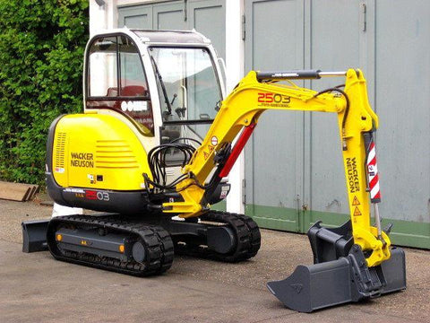
Neuson 50Z3 Track Excavator Workshop Service & Repair Manual # 1 Download
Neuson 50Z3 Track Excavator Workshop Service & Repair Manual
With this in-depth & highly detailed manual you will be able to work on your vehicle with the absolute best resources available, which will not only save you money in repair bills but will also help you to look after your investment, keeping your vehicle in pristine condition. With step by step instruction & highly detailed exploded pictures to show you how to complete the required job correctly & efficiently.
Covers the entire vehicle from start to finish, below is an example of the topics this manual covers, an absolute wealth of information at your fingertips.
Model Covered:
Neuson 50Z3 Track Excavator
Service Manual Covers:
Operation
Important information on this service manual 1-1
Identification of warnings and dangers 1-2
Designated use and exemption from liability 1-3
Type labels and component numbers 1-4
Machine: overview 1-6
Cab overview 1-7
Cab (legend) 1-8
Instrument panel up to serial no. AC02877: overview 1-9
Instrument panel up to serial no. AC02877: legend 1-10
Instrument panel from serial no. AC02893 to serial no. AD07125: overview 1-11
Instrument panel from serial no. AC02893 to serial no. AD07125: legend 1-12
Control elements 50Z3 (from serial no. AH00579) 1-13
Engine compartment up to serial no. AD07125: overview 1-15
Engine compartment (from serial no. AH00579): overview 1-16
Chassis overview 1-17
Tilting the cab 1-18
Summer/winter operation 1-20
Preheated fresh air 1-20
Turning the auxiliary hydraulics/boom swivel pedal around 1-21
Specifications
Chassis 2-1
Engine 2-1
Fuel injection pump 2-2
Engine capacities 2-2
Engine tightening torques 2-2
Hydraulic system 2-3
Auxiliary hydraulics oil flow 2-3
Screwable hose burst valve 2-4
Undercarriage and swivel unit 2-4
Stabiliser blade 2-4
Electric system 2-4
Fuse box in instrument panel
Main fuse box with relays underneath the cab 2-5
Relays 2-5
Noise levels 2-6
Vibration 2-6
Coolant compound table 2-6
Model-specific tightening torques 2-7
General tightening torques 2-7
Tightening torques for hydraulic screw connections (dry assembly) 2-7
Tightening torques for high-resistance screw connections 2-9
Dimensions model 50Z3 2-10
Lift capacity table 50Z3 2-11
Lift capacity table 50Z3 with long stick 2-12
Lift capacity table 50Z3 with counterweight 2-13
Lift capacity table 50Z3 with long stick and counterweight 2-14
Kinematics 2-15
Attachments 2-16
Maintenance
Fluids and lubricants 3-1
Additional oil change and filter replacement (hydraulics) 3-2
Maintenance label 3-3
Explanation of symbols on the maintenance label 3-3
Maintenance plan (overview) 3-5
Service package 3-8
Up to serial no.: AD07125 3-8
From serial no.: AH00579 3-8
Introduction 3-8
Fuel system 3-9
Specific safety instructions 3-9
Refuelling 3-9
Stationary fuel pumps 3-10
Diesel fuel specification 3-10
Bleeding the fuel system 3-10
Emptying the fuel tank 3-11
Fuel prefilter with water separator 3-11
Replacing the fuel filter 3-12
Engine lubrication system 3-13
Checking the oil level 3-13
Filling up engine oil 3-14
Changing engine oil 3-15
Replacing the engine oil filter cartridge 3-16
Cooling system 3-17
Specific safety instructions 3-17
Checking/filling up coolant 3-18
Draining coolant 3-19
Air filter 3-20
Replacing the filter 3-21
Functional check once a week of the dust valve 3-22
V-belt 3-23
Checking V-belt tension 3-23
Retightening the V-belt 3-24
Checking the V-belt of the air conditioning system 3-25
Tightening the V-belt of the air conditioning system 3-26
Pressure check 3-27
General 3-27
Checking pilot control pressure 3-27
Pressure check of variable displacement pump P1 3-28
Pressure check of variable displacement pump P2 3-29
Pressure check of gear pump P3 3-30
Secondary pressure limiting valve of the gear motor 3-30
Measuring ports: overview 3-31
Primary pressure limiting valves 3-31
Test report 3-32
Hydraulic system 3-35
Specific safety instructions 3-35
Checking the hydraulic oil level 3-36
Filling up hydraulic oil 3-37
Changing hydraulic oil 3-37
Monitoring the hydraulic oil reflux filter 3-38
Checking hydraulic pressure lines 3-39
Travelling drive 3-40
Checking the oil level and filling up oil 3-40
Draining oil 3-40
Chains 3-41
Checking chain tension 3-41
Setting the chains 3-42
Lubrication work 3-43
Stabiliser blade 3-43
Lubrication points on the swivelling console
Boom lubrication points 3-44
Lubrication points on the stick 3-44
Lubrication strip 3-45
Maintenance of attachments 3-45
Electric system 3-46
Specific safety instructions 3-46
Service and maintenance work at regular intervals 3-46
Instructions concerning specific components 3-47
Alternator 3-47
Battery 3-48
Cab 3-49
Replacing the cab filter 3-49
General maintenance work 3-50
Cleaning 3-50
General instructions for all areas of the machine 3-50
Inside the cab 3-51
Exterior of the machine 3-51
Engine compartment 3-51
Screw connections and attachments 3-51
Pivots and hinges 3-51
Engine
Engine 4TNV88-PNS (up to serial no. AD07125): overview 4-1
Fuel system 4-3
Checking and adjusting valve clearance 4-4
Tightening order for cylinder head bolts 4-5
Checking the injection nozzles 4-6
Pressure check 4-6
Checking the nozzle jet 4-6
Injection time 4-7
Checking injection time 4-7
Setting injection time 4-7
Replacement of fuel injection pump 4-8
Adjusting engine revs 4-9
Compression 4-9
Checking the coolant thermostat 4-9
Checking the thermal switch 4-10
Oil pressure switch 4-10
Checking the coolant circuit 4-11
Engine 4TNV88-PNS (from serial no. AH00579): overview 4-12
Fuel system 4-14
Removing the valve cover 4-15
Checking and adjusting valve clearance 4-15
Tightening order for cylinder head bolts 4-16
Checking the injection nozzles 4-17
Pressure check 4-17
Checking the nozzle jet 4-17
Injection time 4-18
Checking injection time 4-18
Setting injection time 4-19
Replacement of fuel injection pump 4-20
Adjusting engine revs 4-21
Compression 4-21
Checking the coolant thermostat 4-21
Checking the thermal switch 4-22
Oil pressure switch 4-22
Checking the coolant circuit 4-23
Engine trouble
Hydraulic system
Hydraulic pump PVD-2B-44BP-16G5-4713F (up to AD07125)
PVD-2B-41BP-16G5-4713F (from AH00579) 5-1
Pump unit: exploded view 5-3
Pilot oil supply unit 5-5
Main valve block 5-6
Ports 5-6
Legend 5-7
Main valve block diagram 5-8
Pressure limiting valves 5-9
Pump assignment 5-10
Drive counterbalancing system 5-11
Pump assignment for drive counterbalancing 5-11
Drive counterbalancing system with boom and right-hand side drive activation
Regeneration stick section 5-13
Bucket pre-tension 5-13
Flow rate adjustment of auxiliary hydraulics 5-14
Pilot valves 5-15
Joystick 5-15
Pilot valve (driving) 5-17
Pilot valve for auxiliary hydraulics 5-19
Pilot valve for stabiliser blade 5-20
Valves 5-21
7/2 directional valve (changeover valve) 5-21
4/3 directional valve 5-22
Shuttle valve block 5-23
Changeover valve for SAE/ISO controls (option) 5-24
Travelling drive 5-25
Function 5-26
2nd speed range function 5-26
Swivel unit 5-29
Parking brake/multidisc brake function 5-30
Swivel joint 5-35
Breather filter 5-36
Troubleshooting in the hydraulic system 5-37
Hydraulics diagram A4 5-38
Hydraulics diagram (legend) 5-39
Hydraulics diagram 50Z3 A3 5-41
Options diagram 1 5-42
Options diagram 2 5-43
Main valve block diagram 50Z3 A3 5-44
Electric system
Ohm's Law (current, voltage, resistance); power 6-1
Measuring equipment, measuring methods 6-1
Cable colour coding 6-3
Relays 6-3 Please email at ireneroberson9@gmail.com and we will provide you with the any manual you need right away. We are constantly updating the site with new stock but we have much more than available in the website.
With this in-depth & highly detailed manual you will be able to work on your vehicle with the absolute best resources available, which will not only save you money in repair bills but will also help you to look after your investment, keeping your vehicle in pristine condition. With step by step instruction & highly detailed exploded pictures to show you how to complete the required job correctly & efficiently.
Covers the entire vehicle from start to finish, below is an example of the topics this manual covers, an absolute wealth of information at your fingertips.
Model Covered:
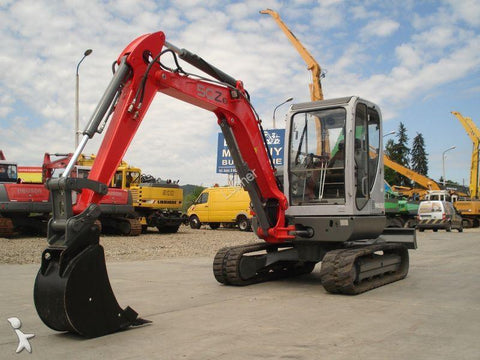
Neuson 50Z3 Track Excavator
Service Manual Covers:
Operation
Important information on this service manual 1-1
Identification of warnings and dangers 1-2
Designated use and exemption from liability 1-3
Type labels and component numbers 1-4
Machine: overview 1-6
Cab overview 1-7
Cab (legend) 1-8
Instrument panel up to serial no. AC02877: overview 1-9
Instrument panel up to serial no. AC02877: legend 1-10
Instrument panel from serial no. AC02893 to serial no. AD07125: overview 1-11
Instrument panel from serial no. AC02893 to serial no. AD07125: legend 1-12
Control elements 50Z3 (from serial no. AH00579) 1-13
Engine compartment up to serial no. AD07125: overview 1-15
Engine compartment (from serial no. AH00579): overview 1-16
Chassis overview 1-17
Tilting the cab 1-18
Summer/winter operation 1-20
Preheated fresh air 1-20
Turning the auxiliary hydraulics/boom swivel pedal around 1-21
Specifications
Chassis 2-1
Engine 2-1
Fuel injection pump 2-2
Engine capacities 2-2
Engine tightening torques 2-2
Hydraulic system 2-3
Auxiliary hydraulics oil flow 2-3
Screwable hose burst valve 2-4
Undercarriage and swivel unit 2-4
Stabiliser blade 2-4
Electric system 2-4
Fuse box in instrument panel
Main fuse box with relays underneath the cab 2-5
Relays 2-5
Noise levels 2-6
Vibration 2-6
Coolant compound table 2-6
Model-specific tightening torques 2-7
General tightening torques 2-7
Tightening torques for hydraulic screw connections (dry assembly) 2-7
Tightening torques for high-resistance screw connections 2-9
Dimensions model 50Z3 2-10
Lift capacity table 50Z3 2-11
Lift capacity table 50Z3 with long stick 2-12
Lift capacity table 50Z3 with counterweight 2-13
Lift capacity table 50Z3 with long stick and counterweight 2-14
Kinematics 2-15
Attachments 2-16
Maintenance
Fluids and lubricants 3-1
Additional oil change and filter replacement (hydraulics) 3-2
Maintenance label 3-3
Explanation of symbols on the maintenance label 3-3
Maintenance plan (overview) 3-5
Service package 3-8
Up to serial no.: AD07125 3-8
From serial no.: AH00579 3-8
Introduction 3-8
Fuel system 3-9
Specific safety instructions 3-9
Refuelling 3-9
Stationary fuel pumps 3-10
Diesel fuel specification 3-10
Bleeding the fuel system 3-10
Emptying the fuel tank 3-11
Fuel prefilter with water separator 3-11
Replacing the fuel filter 3-12
Engine lubrication system 3-13
Checking the oil level 3-13
Filling up engine oil 3-14
Changing engine oil 3-15
Replacing the engine oil filter cartridge 3-16
Cooling system 3-17
Specific safety instructions 3-17
Checking/filling up coolant 3-18
Draining coolant 3-19
Air filter 3-20
Replacing the filter 3-21
Functional check once a week of the dust valve 3-22
V-belt 3-23
Checking V-belt tension 3-23
Retightening the V-belt 3-24
Checking the V-belt of the air conditioning system 3-25
Tightening the V-belt of the air conditioning system 3-26
Pressure check 3-27
General 3-27
Checking pilot control pressure 3-27
Pressure check of variable displacement pump P1 3-28
Pressure check of variable displacement pump P2 3-29
Pressure check of gear pump P3 3-30
Secondary pressure limiting valve of the gear motor 3-30
Measuring ports: overview 3-31
Primary pressure limiting valves 3-31
Test report 3-32
Hydraulic system 3-35
Specific safety instructions 3-35
Checking the hydraulic oil level 3-36
Filling up hydraulic oil 3-37
Changing hydraulic oil 3-37
Monitoring the hydraulic oil reflux filter 3-38
Checking hydraulic pressure lines 3-39
Travelling drive 3-40
Checking the oil level and filling up oil 3-40
Draining oil 3-40
Chains 3-41
Checking chain tension 3-41
Setting the chains 3-42
Lubrication work 3-43
Stabiliser blade 3-43
Lubrication points on the swivelling console
Boom lubrication points 3-44
Lubrication points on the stick 3-44
Lubrication strip 3-45
Maintenance of attachments 3-45
Electric system 3-46
Specific safety instructions 3-46
Service and maintenance work at regular intervals 3-46
Instructions concerning specific components 3-47
Alternator 3-47
Battery 3-48
Cab 3-49
Replacing the cab filter 3-49
General maintenance work 3-50
Cleaning 3-50
General instructions for all areas of the machine 3-50
Inside the cab 3-51
Exterior of the machine 3-51
Engine compartment 3-51
Screw connections and attachments 3-51
Pivots and hinges 3-51
Engine
Engine 4TNV88-PNS (up to serial no. AD07125): overview 4-1
Fuel system 4-3
Checking and adjusting valve clearance 4-4
Tightening order for cylinder head bolts 4-5
Checking the injection nozzles 4-6
Pressure check 4-6
Checking the nozzle jet 4-6
Injection time 4-7
Checking injection time 4-7
Setting injection time 4-7
Replacement of fuel injection pump 4-8
Adjusting engine revs 4-9
Compression 4-9
Checking the coolant thermostat 4-9
Checking the thermal switch 4-10
Oil pressure switch 4-10
Checking the coolant circuit 4-11
Engine 4TNV88-PNS (from serial no. AH00579): overview 4-12
Fuel system 4-14
Removing the valve cover 4-15
Checking and adjusting valve clearance 4-15
Tightening order for cylinder head bolts 4-16
Checking the injection nozzles 4-17
Pressure check 4-17
Checking the nozzle jet 4-17
Injection time 4-18
Checking injection time 4-18
Setting injection time 4-19
Replacement of fuel injection pump 4-20
Adjusting engine revs 4-21
Compression 4-21
Checking the coolant thermostat 4-21
Checking the thermal switch 4-22
Oil pressure switch 4-22
Checking the coolant circuit 4-23
Engine trouble
Hydraulic system
Hydraulic pump PVD-2B-44BP-16G5-4713F (up to AD07125)
PVD-2B-41BP-16G5-4713F (from AH00579) 5-1
Pump unit: exploded view 5-3
Pilot oil supply unit 5-5
Main valve block 5-6
Ports 5-6
Legend 5-7
Main valve block diagram 5-8
Pressure limiting valves 5-9
Pump assignment 5-10
Drive counterbalancing system 5-11
Pump assignment for drive counterbalancing 5-11
Drive counterbalancing system with boom and right-hand side drive activation
Regeneration stick section 5-13
Bucket pre-tension 5-13
Flow rate adjustment of auxiliary hydraulics 5-14
Pilot valves 5-15
Joystick 5-15
Pilot valve (driving) 5-17
Pilot valve for auxiliary hydraulics 5-19
Pilot valve for stabiliser blade 5-20
Valves 5-21
7/2 directional valve (changeover valve) 5-21
4/3 directional valve 5-22
Shuttle valve block 5-23
Changeover valve for SAE/ISO controls (option) 5-24
Travelling drive 5-25
Function 5-26
2nd speed range function 5-26
Swivel unit 5-29
Parking brake/multidisc brake function 5-30
Swivel joint 5-35
Breather filter 5-36
Troubleshooting in the hydraulic system 5-37
Hydraulics diagram A4 5-38
Hydraulics diagram (legend) 5-39
Hydraulics diagram 50Z3 A3 5-41
Options diagram 1 5-42
Options diagram 2 5-43
Main valve block diagram 50Z3 A3 5-44
Electric system
Ohm's Law (current, voltage, resistance); power 6-1
Measuring equipment, measuring methods 6-1
Cable colour coding 6-3
Relays 6-3 Please email at ireneroberson9@gmail.com and we will provide you with the any manual you need right away. We are constantly updating the site with new stock but we have much more than available in the website.